Development
Demonstrator Engine
Dynamic Tests
Flight Programme
Results of the Feasibility Study
The two technical objectives of the study were the derivation of a thrust equation and the verification of that equation by experiment.
The complete static thrust equation is:
 Equation 1.
which can be simplified to

where
T = Thrust in Newtons
P = Power in Watts
Qu = Unloaded Q
D = Design Factor
A full derivation of the equation is given in the theory paper.
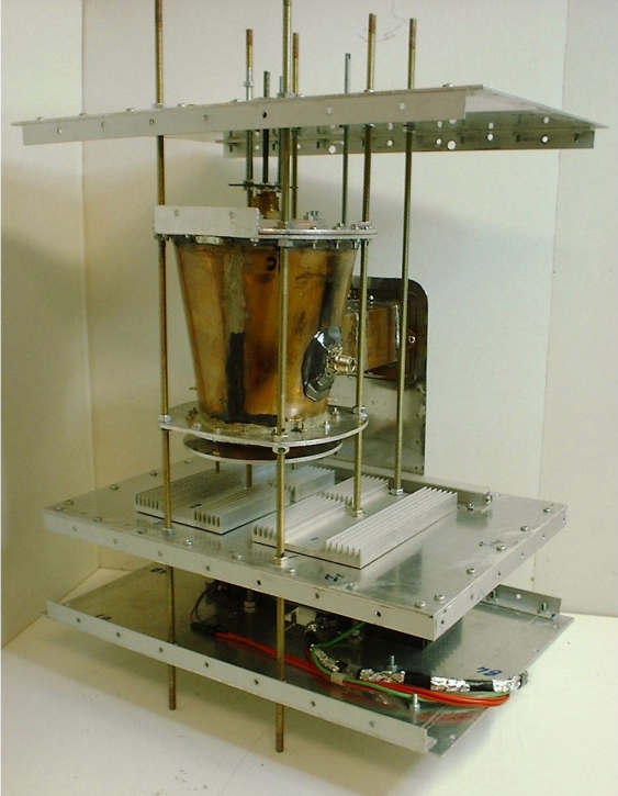
A 160 mm diameter experimental thruster, operating at 2450 MHz was designed and built. (see fig 2)

Fig 2. Experimental thruster.
The design factor, calculated from as-built measurements of the thruster geometry was 0.497. An unloaded Q of 5,900 was measured. The maximum thrust, measured using a precision balance was 16mN for an input power of 850W, which is very close to the thrust of 16.6mN predicted from equation 1.
The thrust could be varied from zero to maximum by varying the input power, or by varying the resonant frequency of the thruster. Considerable efforts were made to test for possible thermal and electromagnetic spurious effects. The primary method was to carry out all tests in both nominal and inverted orientations, and to take the mean of the results. The thruster was also sealed into a hermetic enclosure to eliminate buoyancy effects of the cooling air. Three different types of test rig were used, two using 1 mg resolution balances in a counterbalance test rig and one using a 100 mg resolution balance in a direct measurement of thruster weight.
Comparison of the rates of increase of thrust for the different spring constants, using pulsed input power, gave a clear proof that the thrust was produced by momentum transfer and was not due to any “undefined” spurious effect.
The total test programme encompassed 450 test runs of periods up to 50 seconds, using 5 different magnetrons.